You turn the key, the engine spins over, and it still won't start. Or it starts, runs for a bit, then cuts out at the worst possible moment. In the workshop, those faults always put one small part high on the suspect list. The crankshaft position sensor, often shortened to CKP sensor.
It's not a glamorous component. You don't see it when you open the bonnet, and most drivers never hear about it until there's a problem. But if you've ever asked what does a crankshaft position sensor do, the short answer is this. It tells the engine computer exactly how fast the crankshaft is turning and exactly where it is in its rotation, so the engine knows when to fire the spark and inject fuel.
Get that signal right and the engine runs properly. Lose it and the car may crank forever, stall without warning, or refuse to restart. That's why this sensor matters to DIY owners and trade garages alike.
Your Engine's Unsung Hero The Crankshaft Position Sensor
The car comes in after a school run or an early shift. It cranks at normal speed, the battery sounds fine, and there is no obvious mechanical noise. Still, it will not fire. In cases like that, one of the first questions is simple. Is the ECU getting a believable crank signal?
That question matters because the sensor is watching the engine's basic reference point. The crankshaft is the part turning piston movement into rotation, and the sensor follows that movement closely enough for the management system to decide whether to allow spark and fuel at all. If you want a clearer view of the component the sensor is monitoring, it helps to see where the crankshaft sits in the engine assembly.
A bad crank sensor can create faults that feel much bigger than the part itself. The car may crank and not start. It may cut out hot, then restart after ten minutes on the hard shoulder. It may log a fault code, or it may leave very little behind apart from an intermittent no-start. That is why this fault catches out both DIY owners and good technicians. The symptoms can point in several directions unless you test in a sensible order.
Practical rule: If an engine cranks strongly but will not fire, check whether the ECU can see crank speed and crank position before you start throwing parts at it.
On older engines, you could often get a long way with basic ignition checks and fuel checks. On modern engines, the crankshaft position sensor sits much closer to the centre of the decision-making. If its signal drops out, the ECU may stop spark, stop injector pulse, or both. The result can look like an ignition fault, a fuel fault, or even an immobiliser issue when the actual problem is the missing timing input.
That is also why a proper diagnosis path matters. Start with fault codes and live data if the car supports it. Move to wiring and power supply checks with a multimeter. Use a scope when the fault is intermittent, heat-related, or too fast to catch any other way. That tiered approach saves time in the garage and saves money on the driveway.
How a Crankshaft Sensor Works The Engine's Master Clock
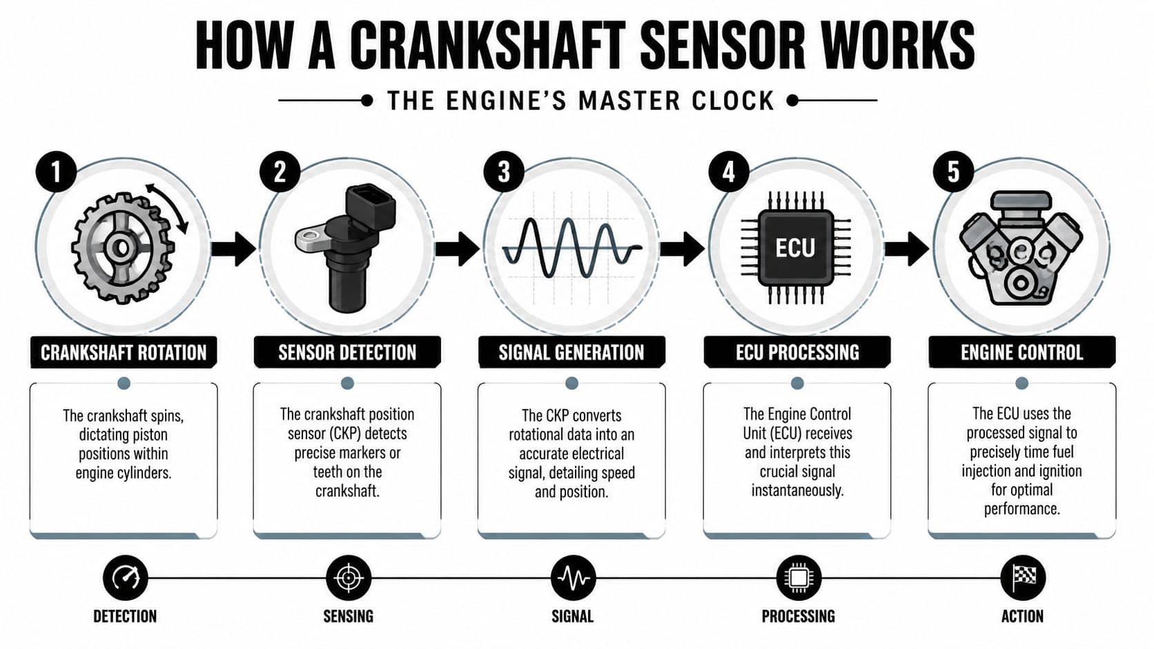
Turn the key on a cold morning and the engine fires almost straight away. That only happens because the ECU knows exactly how fast the crankshaft is turning and where it is in its rotation. The crankshaft position sensor supplies that timing reference from the first few turns of the starter.
If the signal is weak, late, or missing, ignition and injection timing quickly fall apart. On some cars, the ECU will not command spark or injector pulse until it trusts that crank signal.
What the sensor is actually reading
The sensor reads a reluctor wheel, sometimes called a trigger wheel, fixed to the crankshaft assembly. As the teeth pass the tip of the sensor, they create a repeating signal. A gap in that pattern gives the ECU a reference point, so it can work out crank angle rather than just engine speed.
In the workshop, that detail matters. If the wheel is damaged, fitted out of line, or contaminated with swarf, the fault can look exactly like a bad sensor. The same goes for an incorrect air gap. A sensor can be electrically sound and still produce a poor signal if it sits too far from the wheel.
Two common sensor types
Most vehicles you will test use one of two designs, and the test method changes depending on which one is fitted.
Magnetic inductive sensor
This is common on older systems and still turns up on plenty of everyday cars. It contains a magnet and a coil. As the teeth move past, the changing magnetic field generates an AC voltage signal.
On a scope, the waveform is usually a sine wave that grows stronger as cranking speed rises. On a multimeter, you may only catch a rough AC reading, which is why a scope is the better tool when the fault is intermittent or the car only fails hot.
Hall effect sensor
Hall sensors are more common on newer engines. They use a power supply and switch a digital signal on and off as the trigger points pass the sensor face.
On a scope, that appears as a square wave. During cranking, this cleaner low-speed signal is often easier for the ECU to process than the output from an inductive sensor.
The crank signal is only part of the picture. The ECU often compares it with the camshaft position sensor used for phase timing confirmation, especially on sequential injection and modern variable valve timing systems.
Why the ECU depends on it
The ECU uses the crank signal as its base timing input. It sets spark timing from it, schedules fuel delivery from it, and on many engines it also uses small changes in crank speed to monitor for misfire.
That is why diagnosis needs to follow a sensible ladder. Start with scan data to see whether RPM is present while cranking. If that looks wrong or drops out, move to wiring, power, earth, and resistance checks where they apply. If the readings still do not match the fault, put a scope on it and watch the waveform under cranking, idle, and hot restart conditions.
That practical order suits both driveway checks and trade diagnostics. It stops you guessing, and it helps separate a failed sensor from a wiring fault, a damaged reluctor wheel, or a cam and crank correlation problem.
Symptoms of a Failing Crankshaft Position Sensor
When a crank sensor starts failing, the symptoms can look like ignition trouble, fuelling trouble, or an electrical fault elsewhere. The pattern matters more than any one symptom on its own.
What drivers usually notice first
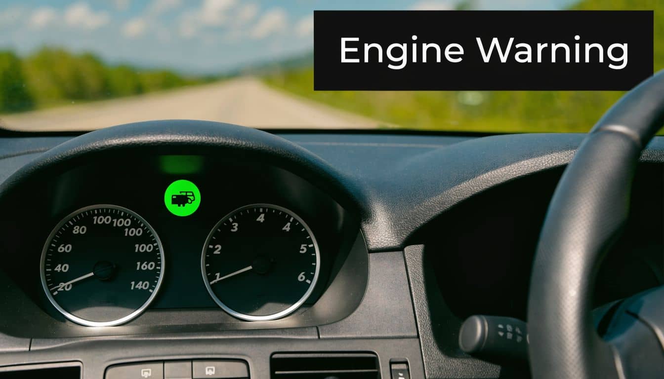
The classic complaint is a crank but no start. The engine turns over, but because the ECU isn't receiving a trustworthy crank signal, it can't time ignition and injection properly enough to get the engine running.
The next common pattern is intermittent stalling. That often shows up once the engine is warm. A weak sensor can produce a poor signal when heat builds up, then behave again after cooling down.
You can also get:
Rough idle: Timing control becomes unstable when the signal is erratic.
Hesitation under load: The ECU loses confidence in engine position data.
Misfire-related warning light: Speed variations across crank rotation can trigger fault monitoring.
Sudden cut-out while driving: The signal may drop out altogether.
A faulty crank sensor often feels like an ignition switch problem because the engine can stop so abruptly.
If your car won't fire at all, a broader car won't start troubleshooting guide can help rule out battery, starter, and fuel issues before you pin everything on the sensor.
Fault codes worth checking
A code reader gives you a much stronger starting point than guesswork. Crankshaft sensor faults often set codes in the P0335 range.
Code | Description |
P0335 | Crankshaft Position Sensor A Circuit |
P0336 | Crankshaft Position Sensor A Circuit Range/Performance |
Those code descriptions are commonly recognised in workshop practice, but codes alone don't prove the sensor itself has failed. Wiring damage, a connector issue, excessive air gap, or reluctor wheel damage can point the scan tool in the same direction.
What works and what doesn't
A lot of people replace coils, plugs, or injectors first because the symptoms overlap. Sometimes that fixes the car. Often it doesn't.
What works is matching the symptom to the sensor's actual job:
No-start: The ECU may have no usable crank reference.
Stall when hot: Heat-sensitive signal loss is a real pattern.
Warning light with driveability issues: The ECU may be seeing an implausible crank signal.
What doesn't work is fitting parts based only on a dashboard light and hope.
How to Test a Crankshaft Position Sensor
A proper crank sensor test starts with the least invasive check and works upward. Read what the ECU can see first, then verify the circuit with a meter, and use a scope if the fault only shows up under load, when hot, or once the engine has been running for a while. That approach saves time and stops good parts being replaced.
First step with an OBD scanner
Plug in a scan tool and check stored codes, pending codes, and live data. The key question during cranking is simple. Does the ECU see engine speed?
If the starter is turning the engine but the scan tool shows no RPM signal, the ECU may be missing the crankshaft reference. That does not prove the sensor itself has failed, because damaged wiring, poor terminal contact, or reluctor problems can produce the same result, but it gives you a strong direction before you reach for tools.
Live data also helps with intermittent faults. On some cars, the RPM signal drops out for a split second before the engine cuts. If you can catch that pattern, you are already further ahead than a basic code read.
The CKP sensor also feeds functions tied to timing and misfire monitoring, which is why crank signal faults can trigger wider running issues than many drivers expect, as explained in Innova's guide to crankshaft and camshaft position sensors.
Multimeter checks for DIY diagnosis
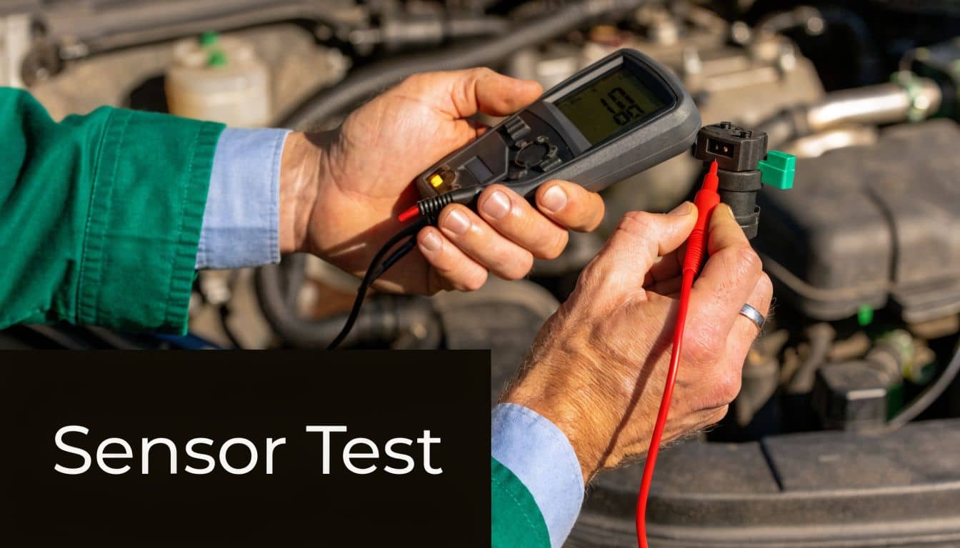
A multimeter is the next sensible step for most UK DIYers. It will not show the full waveform, but it can confirm whether the sensor and its circuit are broadly behaving as they should.
On an inductive sensor
Unplug the sensor and measure resistance across its terminals. Compare the reading with workshop data for that exact engine. There is no single correct value across all makes. An open circuit or a dead short is a bad sign straight away.
Then check AC voltage output while cranking. An inductive sensor generates its own signal, so you should see a changing AC reading as the engine turns. Very low output, no output, or a reading that appears and disappears can all support a crank sensor fault.
On a Hall effect sensor
A Hall sensor is tested differently. It normally has a power supply, an earth, and a signal wire. First confirm the supply and ground are present. Then back-probe the signal wire during cranking and check whether it switches cleanly.
Plenty of home diagnostics go wrong at this stage. An inductive sensor and a Hall sensor do different jobs electrically, so using the same test method on both can send you in the wrong direction.
Workshop habit: Identify the sensor type before you touch the meter. That one step avoids a lot of wasted diagnosis.
Check the basics around the sensor
Before calling the sensor faulty, inspect the parts around it carefully. Crank sensor faults are often sensor circuit faults.
Connector condition: Check for oil ingress, green corrosion, spread terminals, or a broken locking tab.
Wiring route: Look for chafing, heat damage, stretched sections, or repairs hidden in loom tape.
Sensor mounting and air gap: If the gap is wrong, signal strength can fall off, especially during cranking.
Reluctor wheel condition: Damaged teeth, debris, rust build-up, or movement on the wheel can corrupt the signal.
Metal swarf on a magnetic tip is easy to miss. So is a connector that looks plugged in but does not grip the pins properly.
For a visual walkthrough of testing methods, this video is a useful reference before you start probing wires on the car: Crankshaft Position Sensor Test
Oscilloscope testing for a proper answer
If you have access to a scope, use it. This is the clearest way to see the sensor signal during cranking, idle, and the fault condition itself.
An inductive sensor should produce a smooth sine-wave style pattern. A Hall effect sensor should produce a clean square-wave style pattern. The shape matters, but consistency matters more. Dropouts, weak amplitude, extra noise, or an uneven pattern are often more useful than a static voltage reading.
A scope comes into its own with heat-related faults. I see this regularly in the workshop. The car starts and runs from cold, then cuts out once the engine bay warms up. Leave it for twenty minutes and it starts again. In cases like that, a resistance check on a cold sensor can look fine, while the waveform disappears once heat gets into the sensor or wiring.
For same-day diagnosis and repair, many garages and DIY owners source replacement sensors through motor factor networks such as GSF Car Parts, especially when they need to match the part by registration or collect locally.
A General Guide to Crankshaft Sensor Replacement
You can prove a crank sensor fault in ten minutes, then spend an hour getting your hand on it. Access is what turns this from a quick job into an awkward one. Some sensors sit in plain view near the crank pulley. Others are tucked down by the bellhousing where one awkward bolt and a brittle connector can slow everything down.
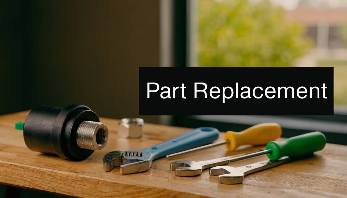
Before you remove anything, make sure replacement is justified. If the fault code, live data, and basic electrical checks all point to the sensor or its short section of wiring, then changing it makes sense. That saves the common mistake of fitting a new part when the actual problem is poor wiring, metal debris on the tip, or a damaged reluctor wheel.
Disconnect the battery. Then get the car safely supported if access is from underneath, remove any covers that are in the way, and clean around the sensor before unplugging it. Grit around the mounting hole can stop the new sensor from seating properly, which can create the same symptoms you started with.
Typical mounting points are:
Near the crank pulley
In the engine block
At the bellhousing, reading the flywheel or flexplate
The basic job is simple. The details are where people get caught out.
Unplug the connector and inspect the lock tab, pins, and wiring close to the plug.
Remove the retaining bolt with the correct socket. A wobble extension often helps in tight spaces.
Work the old sensor out carefully if it has stuck in the bore. Twisting gently is better than prising against alloy casings.
Compare the new part with the old one side by side. Check the connector, body length, mounting face, O-ring position, and bracket shape.
Fit the new sensor squarely and route the wiring exactly as the factory did, away from exhaust heat, belts, and sharp edges.
If the sensor does not sit flush, stop there. Dirt on the mounting face, a swollen O-ring, corrosion in the bore, or the wrong sensor are all more likely than a part that just needs extra force.
Some applications set the gap automatically because the sensor bottoms out on its mounting face. Others depend on the correct spacer, bracket, or sensor design to place the tip at the right distance from the trigger wheel. As noted earlier, that clearance is small enough that dirt, a bent bracket, or the wrong pattern part can weaken or distort the signal.
That matters in practice. A car may crank and nearly fire, start cold and fail hot, or log an intermittent crank signal fault even with a brand-new sensor fitted. In the workshop, that is the point where I stop blaming the new part and start checking fit, wiring tension, and whether the replacement matches the original sensor type.
After fitting, reconnect everything, clear the fault codes, and confirm the repair properly. Check for RPM while cranking on the scan tool, make sure the engine starts cleanly, and road test it if safe. For UK DIYers and trade customers, this is the sensible order: prove the fault with scan data first, confirm the wiring if needed with a multimeter or scope, then replace the sensor once the diagnosis supports it.
Choosing the Right Sensor and Getting Back on the Road
You fit a new crank sensor on Saturday morning, clear the code, and the car still cranks with no start. That is usually not bad luck. It is a sign that the replacement part was matched loosely, the sensor type was wrong, or the quality was poor enough to give the ECU a weak or unstable signal.
Buying the right sensor starts with accuracy, not price. Match the vehicle by registration, engine code, and build date where possible, then put the new part beside the old one before it goes anywhere near the engine. Check the connector shape, body length, mounting ear, seal, and sensor tip. If one detail is off, treat it as the wrong part until proved otherwise.
Sensor type matters as much as fit. As noted earlier, some engines use different crank sensor designs that may look similar but produce different signals. A cheap pattern part can bolt in and still cause hard starting, hot non-start faults, poor RPM readings while cranking, or repeat fault codes. In the workshop, that is why I would rather fit a known OE-quality sensor once than do the same job twice with the wrong bargain part.
For UK DIYers, the sensible path is tiered. Start with scan data. If the fault picture is still unclear, move to wiring checks with a multimeter, then scope the signal on harder cases before ordering parts. That approach saves money and avoids guesswork. It also stops a wiring fault or damaged trigger wheel being blamed on a brand-new sensor.
For part sourcing, use a supplier that lets you search by number plate and cross-check against the original part details. GSF Car Parts is one option for finding a replacement crankshaft position sensor, checking availability, and collecting it locally if the car needs to be turned around quickly.
A good crank sensor repair ends with proof, not hope. The engine should show a stable crank RPM signal, start cleanly, and restart hot without dropping out.