Ever wondered how your turbocharged engine delivers that satisfying kick of power without guzzling fuel? The secret lies in a small, yet crucial component: the boost pressure sensor. This sophisticated device acts as a vital communication link, constantly informing the engine's computer how to manage airflow for optimal performance.
At its core, this sensor monitors the air pressure within the engine's intake system and feeds that data back to the Engine Control Unit (ECU), helping it strike the perfect balance between power, fuel efficiency, and emissions control.
What a Boost Pressure Sensor Does for Your Engine
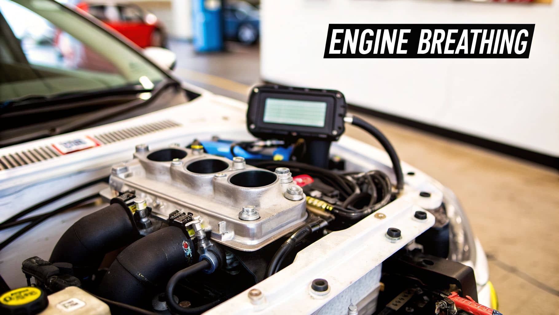
For a modern engine to perform at its peak, it needs to regulate its air intake precisely. The boost pressure sensor is a key instrument in this process, ensuring the engine receives the ideal amount of air for any given driving condition, from idling in traffic to accelerating onto the motorway.
This sensor is also widely known as a Manifold Absolute Pressure (MAP) sensor, particularly in turbocharged vehicles. Its primary function is to measure the air pressure inside the intake manifold—the network of passages that delivers air to the engine's cylinders. This measurement is not a one-off check; it occurs continuously, providing real-time data to the ECU.
This quick-reference table summarises the role of this essential component.
Boost Pressure Sensor Quick Facts
Aspect | Description |
Role | Measures air pressure in the intake manifold and sends data to the ECU. |
Also Known As | Manifold Absolute Pressure (MAP) sensor. |
Location | Typically mounted on or connected to the engine's intake manifold. |
Importance | Crucial for managing the air-fuel mixture, ignition timing, and turbo boost. |
Engine Health | A faulty sensor can cause poor performance, bad fuel economy, and higher emissions. |
This small sensor is fundamental to unlocking an engine's full potential.
The Brains Behind the Brawn
The data transmitted from the boost pressure sensor goes directly to the car's central computer, the Engine Control Unit (ECU). The ECU processes thousands of data signals every second to ensure all engine systems operate in harmony.
Based on the pressure data it receives, the ECU makes instantaneous adjustments to two critical functions:
Fuel Injection: It modulates the amount of fuel injected into the cylinders to achieve the correct stoichiometric ratio with the incoming air.
Ignition Timing: It determines the precise moment to ignite the air-fuel mixture to extract maximum energy from each combustion cycle.
This constant calibration is what gives a turbocharged vehicle its sharp acceleration, respectable fuel economy, and low emissions. If the boost pressure sensor begins to provide inaccurate information, the entire engine management system can be compromised.
An inaccurate boost pressure sensor can lead to a significant decline in fuel efficiency, sometimes by as much as 10-20%. If the ECU receives incorrect signals, it may command an overly rich fuel mixture, where excess fuel is wasted and expelled as unburnt hydrocarbons in the exhaust.
Why This Matters for Both Petrol and Diesel Engines
This technology is indispensable for any modern petrol or diesel engine equipped with a turbocharger. A turbocharger functions by forcing compressed air into the engine, enabling greater power output from a smaller, more efficient engine design. The boost pressure sensor acts as the gatekeeper, informing the ECU of the exact pressure level—or "boost"—the turbo is generating.
You can explore the intricate workings of a turbo and its associated components in our detailed guide on modern turbo systems.
When this sensor starts to fail, the signals it transmits become unreliable. The ECU might interpret a lower-than-actual pressure and reduce fuel delivery, resulting in a frustrating lack of power. Conversely, it might receive a higher-than-actual pressure reading, causing it to over-fuel and produce clouds of black smoke from the exhaust.
Understanding the function of the boost pressure sensor is the first step toward diagnosing issues and maintaining the smooth, efficient operation of your turbocharged vehicle.
How the Sensor Translates Air Pressure into Data
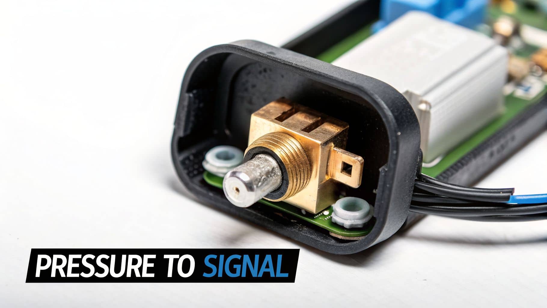
A boost pressure sensor functions as a transducer, converting the physical force of air pressure into an electrical signal that the vehicle’s ECU can interpret instantly. But how does this sophisticated device accomplish this task?
At the core of most boost sensors lies a sensitive component known as a piezoresistive element. This can be visualised as a miniature, flexible silicon diaphragm. One side is sealed within a vacuum, creating a perfect, unchanging reference point. This design allows the sensor to measure the absolute pressure within the intake manifold, rather than just the pressure relative to the outside atmosphere.
When the driver accelerates and the turbocharger forces compressed air into the engine, the pressure inside the intake system rises. This increased pressure causes the diaphragm within the sensor to flex, and the degree of flexion is directly proportional to the amount of boost the turbo is producing.
From Physical Flex to Electrical Signal
This is where the transduction process occurs. As the diaphragm flexes under pressure, its internal electrical resistance changes. This principle is both simple and ingenious: a physical movement induces a measurable electrical change.
The Engine Control Unit (ECU) supplies the sensor with a stable 5-volt reference signal. As the diaphragm flexes and its resistance alters, it modifies this voltage, creating a new output signal that is sent back to the ECU.
This relationship between pressure and voltage is both predictable and linear.
Low Pressure: When the engine is idling or a vacuum exists in the manifold, the diaphragm flexes minimally. This results in a low voltage signal, typically around 1.0 to 1.5 volts.
High Pressure: Under full boost conditions, the diaphragm is deflected significantly. This generates a high voltage signal to the ECU, sometimes reaching as high as 4.5 volts.
The ECU is programmed to interpret these voltage levels precisely. It understands that a 1.2-volt signal corresponds to one pressure level, while a 4.2-volt signal indicates a much higher one. This continuous stream of data enables the ECU to make rapid adjustments to fuel injection and ignition timing, ensuring the engine operates at peak efficiency.
In technical terms, the boost pressure sensor converts the mechanical force of air pressure into a variable voltage signal. This allows the ECU to precisely monitor the turbo’s output, which is fundamental to modern engine management.
The Role of Integrated Circuitry
Modern boost sensors are more than just a simple diaphragm. They incorporate a small integrated circuit that conditions and amplifies the signal before transmission. This onboard processing ensures the signal is accurate and stable, compensating for variables like temperature fluctuations that could otherwise affect the reading.
Furthermore, some advanced sensors integrate an Intake Air Temperature (IAT) sensor. This provides the ECU with two critical data points from a single component, allowing for even more precise calculations of air density—a key factor for optimising the air-fuel mixture. To see the different types available, you can explore our range of MAP sensors for different vehicle models.
Understanding this process—from physical pressure to electrical data—demystifies the sensor's function. It reveals how a simple physical change becomes a powerful command for the engine, providing a solid foundation for confident diagnosis and testing.
Recognising a Failing Boost Pressure Sensor
When a boost pressure sensor begins to fail, it rarely does so silently. Your vehicle will typically exhibit clear, and often frustrating, symptoms indicating that something is wrong. The sensor acts as a translator between the turbocharger and the ECU; if the translation is inaccurate, the engine receives incorrect commands.
Learning to identify these symptoms is the first step in diagnosing the problem effectively.
The most common symptom is a sudden and dramatic loss of power. It can feel as if the turbocharger has ceased to function. You press the accelerator, anticipating a surge of speed, but receive only a sluggish, weak response. This typically occurs because a faulty sensor is under-reporting the boost pressure to the ECU. The ECU then reduces the fuel supply to match this incorrect reading, effectively starving the engine of the fuel it needs to perform.
Another key indicator is the content of the exhaust. If you observe puffs or clouds of black smoke, this is a strong sign that the air-fuel mixture is excessively rich. This is the opposite problem: the sensor is reporting more pressure than is actually present, tricking the ECU into injecting more fuel than the available air can properly combust. This unburnt fuel is then expelled as soot.
Performance and Efficiency Alarms
Beyond power loss and smoke, a failing boost sensor impacts fuel economy and overall driveability. A noticeable drop in fuel efficiency is almost certain. Whether the engine is running too rich or too lean, the air-fuel ratio is incorrect, leading to more frequent trips to the petrol station.
You may also experience these issues:
Rough or Shaky Idle: The engine might struggle to maintain a steady speed when stationary, leading to vibrations and an unstable idle.
Hesitation on Acceleration: When power is demanded, the engine may stumble or pause before responding, resulting in a jerky and unpredictable driving experience.
Engine Warning Light: This is the most direct signal. The illuminated malfunction indicator lamp (MIL) on your dashboard is the ECU’s way of reporting that it has detected a fault with one of its sensors.
A faulty boost sensor has financial implications beyond fuel costs. Fleet operators of light commercial vehicles can see fuel expenditure increase by 10-20% due to inefficient boosting. With average repair bills for turbo-related issues on the rise, it's crucial to address the problem with reliable parts. You can learn more about the pressure sensor market and its impact by exploring the latest industry insights.
Connecting Symptoms to Causes
To assist with diagnosis, this table links common symptoms to their underlying causes within the sensor's operation. Understanding why a vehicle exhibits certain behaviours makes it easier to pinpoint the root of the problem.
Common Symptoms and Their Underlying Causes
Symptom | Potential Cause Related to Sensor Failure |
Severe Power Loss | The sensor is "under-reading" pressure, causing the ECU to reduce fuel and boost, leading to a weak engine response. |
Black Exhaust Smoke | The sensor is "over-reading" pressure, tricking the ECU into injecting too much fuel, resulting in an overly rich mixture. |
Poor Fuel Economy | The air-fuel ratio is consistently incorrect, leading to inefficient combustion and wasted fuel. |
Rough Idle | Erratic or inconsistent signals from the sensor cause the ECU to constantly adjust fuelling, creating an unstable idle speed. |
Check Engine Light | The ECU has logged a fault code because the sensor's voltage readings are outside their expected range or don't match data from other sensors. |
Ultimately, each of these signs points to a breakdown in communication. The sensor is no longer providing the accurate, real-time data the engine needs to function correctly. By recognising these symptoms early, you can proceed with testing the component and restoring your vehicle to its proper operating condition.
How to Test and Confirm a Faulty Sensor
How To Test The VW Boost Pressure Sensor Testing
Before purchasing a replacement part, it is essential to confirm that the existing boost pressure sensor is indeed the source of the problem. This section outlines a logical diagnostic process, beginning with simple checks and progressing to more detailed tests, enabling a confident diagnosis.
Starting with Your OBD-II Scanner
The most efficient starting point for diagnosis is an On-Board Diagnostics (OBD-II) scanner. If the check engine light is illuminated, connecting this tool to your vehicle's OBD-II port (typically located under the dashboard) will allow you to retrieve any Diagnostic Trouble Codes (DTCs) stored by the ECU.
These codes provide a digital trail that can lead you directly to the source of the fault. For boost pressure sensor issues, several specific codes are commonly flagged.
Here are some of the most common fault codes associated with a failing boost sensor:
P0235 - Turbocharger/Supercharger Boost Sensor "A" Circuit Malfunction: A general code indicating an issue within the sensor's electrical circuit, which could be the sensor, wiring, or connector.
P0236 - Turbocharger/Supercharger Boost Sensor "A" Circuit Range/Performance: This suggests the sensor's readings are implausible. The ECU is detecting data that is outside the expected range when compared to other engine sensor inputs.
P0238 - Turbocharger/Supercharger Boost Sensor "A" Circuit High:
This code is triggered when the ECU receives an abnormally high voltage signal from the sensor, suggesting a potential short circuit or a sensor stuck at its maximum reading.
The presence of these codes strongly indicates that the boost pressure sensor requires further inspection.
A Thorough Visual Inspection
With a fault code identified, the next step is a careful visual inspection. It is not uncommon for the problem to be a simple connection issue rather than a failed sensor. First, ensure the ignition is off. Then, locate the boost pressure sensor—it is typically mounted directly on the intake manifold or a large-diameter boost pipe.
Once located, inspect the following:
The Electrical Connector: Is it securely fastened? Check for any signs of corrosion, dirt, or bent pins. A loose or contaminated connection can disrupt the signal.
The Wiring Harness: Trace the wires from the sensor as far as possible. Look for any cracks, frayed insulation, or signs of heat damage that could cause a short or open circuit.
The Sensor Body: Check for cracks or physical damage. Also, inspect for heavy oil contamination, which can sometimes ingress and interfere with its operation.
Vacuum Hoses: Ensure any nearby vacuum lines are properly attached and free from splits or cracks. A vacuum leak can produce symptoms that mimic a failed sensor.
This decision tree illustrates how various symptoms can guide your diagnostic path.
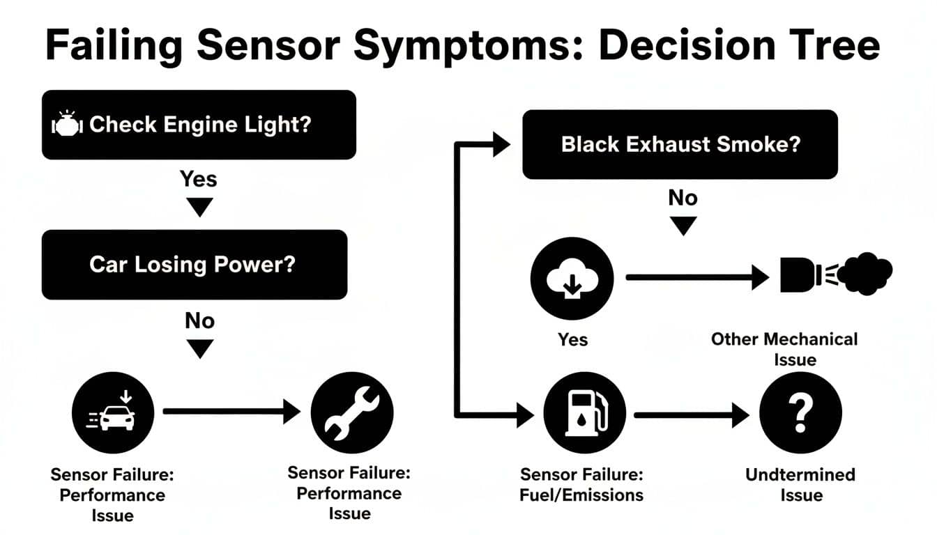
As the flowchart demonstrates, symptoms like black smoke may appear even without a check engine light, underscoring the importance of a comprehensive diagnostic approach.
Testing the Sensor with a Multimeter
If the visual inspection reveals no obvious faults, the next step is to use a multimeter. This is the definitive method for confirming whether the sensor is transmitting the correct electrical signals. You can explore a variety of electrical testers and detectors suitable for automotive diagnostics.
This test involves probing the sensor's wiring to measure its voltage output under different conditions.
Important Safety Note: Some of these steps require the engine to be running. Exercise extreme caution around moving parts such as belts and fans. If you are not comfortable working on a running engine, it is advisable to seek assistance from a qualified mechanic.
Here is a step-by-step guide to testing the sensor:
Identify the Wires: A typical boost sensor has three wires: a 5V reference feed from the ECU, a ground wire, and the signal wire that returns a variable voltage to the ECU. You may need a wiring diagram for your specific vehicle to identify each wire.
Test with Ignition On, Engine Off: Turn the key to the "On" position without starting the engine. Set your multimeter to DC volts. Connect the black probe to a known good ground point on the chassis or engine. Carefully back-probe the signal wire with the red probe. At atmospheric pressure (engine off), the reading should be approximately 1.5 to 2.0 volts.
Test at Idle: Safely start the engine and allow it to idle. The voltage should decrease to around 1.0 to 1.5 volts due to the vacuum created in the intake manifold at idle.
Test Under Pressure (Optional): For a comprehensive test, you can simulate boost with a hand-held vacuum/pressure pump. With the engine off, disconnect the sensor and connect the pump. As you slowly apply pressure, the voltage on the signal wire should increase smoothly and progressively, approaching 4.5 volts at maximum pressure.
If the voltage remains static at zero or 5V, or if it fails to change as expected, you have confirmed a fault. This is a clear indication that the boost pressure sensor has failed and requires replacement.
How to Replace a Boost Pressure Sensor
Having diagnosed a faulty boost pressure sensor, the next step is replacement. This task is well within the capability of most DIY mechanics and offers a great opportunity to avoid a significant garage bill.
This step-by-step guide will walk you through the process to ensure it is done correctly.
Before beginning any work, prioritise safety. The cardinal rule for any task involving a vehicle's electrical system is to disconnect the negative terminal of the battery. This simple step prevents accidental short circuits that could damage other components or cause personal injury. Use a spanner to loosen the nut on the negative terminal and slide the clamp off.
Next, gather the necessary tools. Having everything prepared beforehand streamlines the process.
You will likely need:
A socket set or spanners for the sensor’s mounting bolts.
A flat-head screwdriver for releasing the electrical connector clip if it is stiff.
A clean, lint-free cloth for cleaning the mounting port.
A small amount of silicone lubricant or fresh engine oil for the new O-ring.
The new boost pressure sensor.
With your tools organised and the battery disconnected, you are ready to begin.
Locating and Removing the Old Sensor
The boost pressure sensor is typically easy to find. It is located somewhere on the intake system after the turbocharger. Open the bonnet and trace the pipework from the intercooler to the engine's intake manifold. Look for a small, black plastic component plugged directly into the manifold or a large boost pipe, with a wiring harness connected to it.
Once located, removal involves three simple steps.
Unplug the Connector:Depress the locking tab on the electrical plug and pull it away from the sensor. If it has been in place for a long time, it may be stiff. Gently wiggle it, but never pull on the wires themselves.
Remove the Bolt(s): Using the appropriate socket or spanner, carefully remove the bolt (or sometimes two) securing the sensor. Place it somewhere safe for re-use.
Extract the Sensor: The sensor is sealed by a rubber O-ring, so it will fit snugly. Gently twist the sensor left and right while pulling it upwards to work it free. Avoid trying to remove it with excessive force.
Pro Tip: Examine the old sensor and its mounting port. A significant accumulation of oil or carbon residue may indicate a separate issue with the engine's crankcase ventilation system (e.g., a blocked PCV valve), which may warrant further investigation.
Installing the New Boost Pressure Sensor
Installation is largely the reverse of removal, but a few key details will ensure a professional-quality job and prevent future issues. A perfect seal is critical.
First, prepare the mounting surface. Before unboxing the new part, use a clean cloth to thoroughly wipe the mounting surface and the inside of the port on the intake manifold. Any dirt or debris can compromise the seal, leading to a boost leak and a recurrence of the original problem.
With the area clean, you can proceed with installation.
Lubricate the New O-Ring: Apply a small dab of silicone lubricant or a spot of fresh engine oil to the new sensor’s rubber O-ring. This is a standard mechanic's practice that helps the sensor slide into place without pinching or tearing the seal.
Insert the New Sensor: Carefully press the new sensor into its port. It should seat firmly and sit flush against the manifold.
Secure the Mounting Bolt: Re-install the bolt and tighten it. Be careful not to over-tighten it. The sensor housing is made of plastic and can crack under excessive torque. Tighten until it is snug and secure.
Reconnect the Electrics: Plug the electrical connector back onto the new sensor. A distinct "click" will confirm it is properly locked in place, ensuring a good connection.
Finally, reconnect the negative terminal on your battery and tighten the clamp. The replacement is complete.
Upon starting the engine, the ECU will begin receiving accurate data from the new sensor. The engine management system may require a short drive cycle to fully re-adapt, but you should notice an immediate improvement in performance and throttle response.
Your Boost Sensor Questions Answered
It is normal to have questions about automotive components and repairs. This section addresses some of the most common queries regarding boost pressure sensors to enhance your understanding.
Can I Just Clean My Boost Pressure Sensor?
While it may seem like a cost-effective solution, cleaning a boost pressure sensor is rarely a permanent fix.
A surface clean may remove some oil or carbon deposits, potentially providing a brief, temporary improvement. However, the root cause of failure is typically internal, related to the degradation of the delicate electronic components. Cleaning the exterior plastic housing will not repair a failed internal element. For a lasting and reliable repair, replacement is the only effective solution.
What’s the Difference Between a MAP and a Boost Sensor?
This is a common point of confusion, but the distinction is straightforward. In many cases, they are the same physical part, with the name varying based on the engine application.
On a standard, naturally-aspirated engine (one without a turbo or supercharger), the sensor is called a Manifold Absolute Pressure (MAP) sensor. Its primary function is to measure vacuum within the inlet manifold.
On a turbocharged or supercharged engine, the same type of sensor must also measure positive pressure—what is known as boost. In this application, it is more commonly referred to as a boost pressure sensor.
In essence, all boost pressure sensors are a type of MAP sensor, but not all MAP sensors are used to measure boost pressure. The engine's induction system dictates the component's common name.
What Happens If I Ignore a Failing Sensor?
Delaying this repair is inadvisable, as it can lead to a cascade of more serious and expensive problems. A faulty boost sensor will not resolve itself.
You will certainly experience poor fuel economy and frustrating performance. More importantly, the engine will be operating on an incorrect air-fuel mixture. Over time, this can lead to overheating and failure of the catalytic converter (a very costly replacement). In some cases, the vehicle may enter a restricted-performance ‘limp mode’ to protect the engine from further damage. This small component can cause significant issues if neglected.
For a reliable fix, find the right boost pressure sensor for your vehicle at GSF Car Parts. We offer quality parts from trusted brands to get your car running smoothly again. Click here to find your part.